
In modern cleanroom engineering, the combination of a Fan Filter Unit (FFU) and a terminal mini-pleat HEPA filter acts as the beating heart of controlled environments. While FFU assemblies provide the motorized air delivery and static pressure necessary to drive air through the system, the terminal mini-pleat filter ensures absolute particulate containment under strict ISO 14644 and EU GMP standards.
However, mismatched aerodynamic curves, improper sealing mechanics, or poor dimensional tolerances between the FFU plenum and the filter frame can cause catastrophic failures—ranging from localized air bypass and microbial ingress to excessive acoustic noise and premature motor burnout.
This engineering guide examines the core principles of matching mini-pleat HEPA filters with FFUs, focusing on sealing technology, static pressure coordination, and airflow uniformity.
Note: This technical guide is part of our comprehensive engineering series on terminal filtration. Return to our central Ultimate Engineering Guide to Mini-Pleat HEPA Filters or review our efficiency comparison on H13 vs. H14 Mini-Pleat HEPA Filters.
The FFU-HEPA Symbiosis: Aerodynamic & Mechanical Coupling
An FFU is a self-contained modular air-moving device that integrates an internal blower (typically an energy-efficient Electronically Commutated or EC motor) with a terminal filter housing. The synergy between the FFU blower and the mini-pleat HEPA filter dictates the overall system performance:
Positive Plenum Pressure: Unlike ducted supply systems where filters are placed remotely downstream of the air handling unit, FFUs operate with an internal positive pressure plenum immediately above the HEPA filter face.
Velocity Vector Control: The filter media must act as a precise flow-straightener, converting turbulent or swirling plenum discharge into a uniform, unidirectional laminar air flow (typically maintained at 0.45 m/s +/- 20% at the work surface).
Harmonic Resonance Mitigation: High-speed backward-curved impellers within FFUs generate specific vibration frequencies. The rigid frame construction and uniform hot-melt bead spacing of mini-pleat filters must absorb these vibrational forces without transferring stress to the fragile glass fiber media.

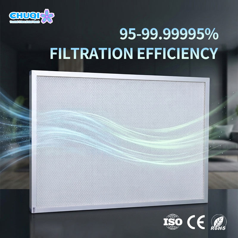
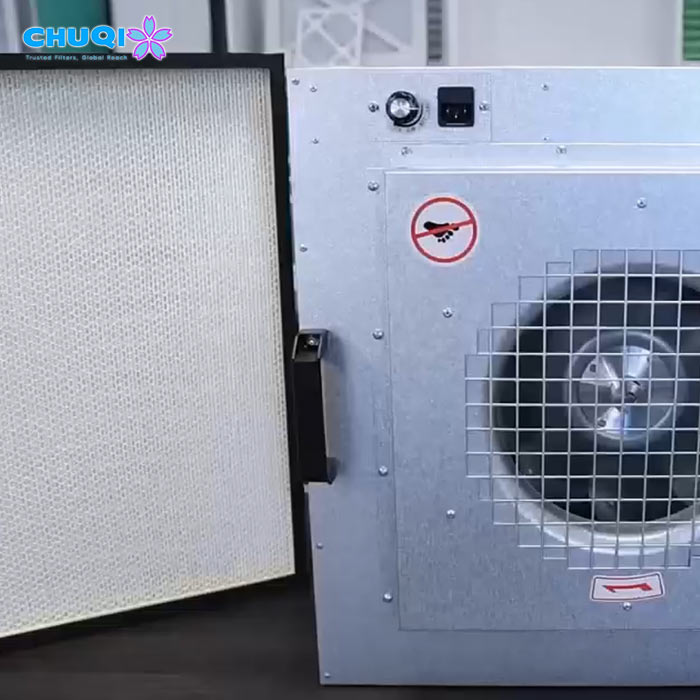
Sealing Technologies: Gel-Seal vs. Knife-Edge vs. Gasket Systems
Preventing air bypass between the high-pressure FFU plenum and the cleanroom space is the single most critical mechanical challenge in terminal assembly. Three primary sealing methods are utilized in modern FFU designs:
A. Liquid Gel Seal Systems (The Gold Standard for Critical Cleanrooms)
Mechanism: The filter frame incorporates an integrated U-shaped channel filled with a non-curing polyurethane or silicone gel. The FFU module features a rigid metal “knife-edge” flange that submerges directly into this viscous gel channel.
Engineering Advantage: Gel-seal technology accommodates thermal expansion, structural deflection, and ceiling grid vibrations while providing an absolute 100% leak-proof barrier. It is the mandatory specification for ISO Class 1 to Class 5 cleanrooms and aseptic pharmaceutical Grade A zones.
B. Knife-Edge with Dry Gasket Compression
Mechanism: A closed-cell neoprene, EPDM, or polyurethane gasket is affixed to either the filter flange or the FFU mounting collar, compressed mechanically via toggle latches or screw clamps.
Engineering Advantage: Cost-effective and widely used in commercial or modular cleanrooms (ISO Class 6 to 8). However, it requires precise torque management during installation to prevent gasket over-compression or localized air channeling.
C. Positive Pressure Gel / Negative Pressure Isolation
In advanced containment hoods, specialized gel seals ensure that any potential micro-leakage is trapped within the negative pressure return loop or captured during mandatory EN 1822 in-situ photometer scan tests.
Aerodynamic Synergy: Balancing Fan Static Pressure and Filter Resistance
A common failure mode in cleanroom commissioning is specifying an FFU motor that lacks adequate static pressure reserve to overcome the terminal resistance of high-efficiency mini-pleat filters over their multi-year lifecycle.
The Resistance Lifecycle Curve:
Clean-State Resistance: A standard H13 or H14 mini-pleat filter exhibits an initial clean-state pressure drop between 80 Pa to 140 Pa at a face velocity of 0.45 m/s.
Dust-Loading Accumulation: As the filter captures sub-micron particulate over time, surface resistance increases progressively.
EC Motor Compensation: Modern FFUs equipped with intelligent EC motor controllers automatically ramp up RPMs to maintain constant air volume against rising static pressure.
Engineering Design Rules:
Static Pressure Headroom: System designers must ensure that the FFU blower curve can deliver the required air change rates even when terminal HEPA resistance reaches its terminal replacement threshold (typically 250 Pa to 300 Pa).
Pleat Geometry Optimization: Mini-pleat filters utilizing hot-melt thermoplastic bead separators provide optimal open area channels, minimizing turbulent eddy currents and reducing unnecessary pressure drop compared to older aluminum separator designs.
Dimensional Tolerances & Installation Integrity Pitfalls
Ceiling grid systems demand rigorous dimensional accuracy between the FFU module and the mini-pleat filter outer frame.
Tolerance Stack-Up: A deviation of just 2 mm to 3 mm in frame squareness can create a gap along the FFU housing perimeter, bypassing the filtration media entirely. Always verify nominal versus actual outer dimensions (e.g., standard 2×4 ft, 2×2 ft, or metric equivalents like 575×1175 mm).
Handling Fragile Media: Mini-pleat wet-laid micro-glass fiber paper is extremely sensitive to mechanical impact. During FFU ceiling installation, technicians must handle filter packs exclusively by the outer frame, avoiding any contact with the delicate pleat pack to prevent micro-punctures that cause failure during PAO/DEHS scan testing.
Commissioning and Operational Maintenance Protocols
The operational reliability and regulatory compliance of an integrated FFU and mini-pleat HEPA filter array depend entirely on rigorous, methodical commissioning (IQ/OQ/PQ) and proactive lifecycle management. Post-installation validation must be executed strictly in accordance with ISO 14644-3 (Test Methods) and EN 1822 / IEST-RP-CC001 standards.
In-Situ Aerosol Challenge Testing (PAO / DEHS Photometric Scan):
Methodology: An aerosol generator (e.g., Laskin nozzle generator) introduces pharmaceutical-grade polyalphaolefin (PAO) or DEHS upstream to establish a stable challenge concentration of 10 to 20 μg/L.
Scan Execution: A calibrated forward-scattering photometer probe is swept across the entire downstream media face, the frame perimeter, and the FFU gel-seal or gasket interface at a traverse rate of no more than 5 cm/sec, maintaining a probe-to-filter distance of approximately 25 mm.
Acceptance Criteria: For H14 terminal HEPA filters, the maximum allowable local penetration rate must not exceed 0.01%, verifying absolute zero bypass leakage across the mechanical sealing boundary.
Air Velocity Profiling & Unidirectional Flow Mapping:
Grid Anemometry: Utilizing calibrated thermal anemometers to measure face velocity across a standardized cross-sectional grid matrix positioned 150 mm to 300 mm below the filter face.
Tolerance Threshold: Maintaining a mean velocity of 0.45 m/s (±20%) to ensure proper displacement of particulate clouds and compliance with ISO 14644 recovery time benchmarks.
Differential Pressure (DP) Lifecycle Tracking & Maintenance Triggers:
Continuous Monitoring: Deploying high-precision magnehelic gauges or digital differential pressure transducers across each FFU module to track real-time resistance evolution.
Replacement Threshold: While clean-state mini-pleat resistance initiates at 80–110 Pa, proactive replacement protocols must be triggered when terminal resistance reaches 250 Pa to 300 Pa, or when localized airflow drops below the minimum sweep threshold required by cleanroom classification.
Technical Summary & Engineering Resources
Properly matching mini-pleat HEPA filters with Fan Filter Units (FFU) is a foundational discipline that governs the long-term cleanliness, regulatory compliance, and energy footprint of any advanced controlled environment.
To continue optimizing your cleanroom engineering parameters, explore our supporting resources:
Central Technical Framework: Return to our foundational Ultimate Engineering Guide to Mini-Pleat HEPA Filters for comprehensive material science specs.
Product Specifications: Review our Mini-Pleat HEPA Filter Series to evaluate custom frame geometries, gel-seal specifications, and pressure-drop performance curves.
Engineering Consultation: For project-specific FFU housing compatibility, custom sizing, or bulk engineering orders, you are invited to connect with our technical team for dedicated engineering support.