
Sizing a HEPA filter for an industrial air system requires more than matching the filter dimensions to an equipment opening. The selected configuration must meet the required airflow, filtration performance, pressure-drop limits and installation requirements under the intended operating conditions.
To size an industrial HEPA filter, first establish the airflow through the HEPA stage. Then evaluate the required filtration class, available pressure, filter dimensions, quantity and housing interface. A face-area calculation can help compare preliminary layouts, but final selection must be verified against product-specific performance data.
This guide explains how engineers, OEM equipment manufacturers, maintenance teams and industrial filtration buyers can estimate the required face area, compare single-filter and parallel-bank arrangements, evaluate system pressure constraints and prepare the information needed to specify a custom or replacement HEPA filter.
What Information Is Needed to Size a HEPA Filter?
Before calculating the required area or selecting a catalogue size, establish the following design inputs.
| Design Input | What to Confirm | Why It Matters |
|---|---|---|
| Required airflow | Airflow through the HEPA stage and relevant operating range | Establishes the duty assigned to the filter or filter bank |
| Filtration performance | Required filtration class and applicable test basis | Constrains acceptable filter configurations |
| Available pressure | Pressure capability available to the HEPA stage at the required airflow | Determines whether candidate filter resistance is acceptable |
| Installation dimensions | Available width, height, depth and supporting space | Limits the physical layout |
| Housing interface | Seals, mounting, retention and airflow orientation | Determines installation and sealing compatibility |
| Operating environment | Relevant temperature, humidity and contaminant exposure | Affects material and construction suitability |
| Maintenance access | Removal path, handling space and replacement procedure | Determines whether the filter can be serviced practically |
If you are developing new equipment, the housing and filter arrangement may still be adjustable. For an upgrade, an existing fan or equipment opening may be the main constraint. For a replacement, the original filter reference, approved drawing and current operating requirements become particularly important.
1. Establish the Airflow Through the HEPA Stage
The first step in HEPA filter sizing is to determine how much air must pass through the relevant filtration stage.
Total equipment airflow, branch airflow and airflow through an individual filter are not necessarily the same. Industrial systems may contain multiple branches, parallel filters, bypass paths or different operating modes.
For example, if an industrial machine handles 3,600 m³/h in total, that figure does not automatically mean every HEPA filter must handle 3,600 m³/h. The required duty depends on the system arrangement and how the total airflow is distributed.
Distinguish Required Airflow from Current Airflow
A measured operating flow describes the equipment under the conditions present during measurement. It does not necessarily represent the required design airflow.
Existing equipment may deliver less air than intended because of filter loading, operating settings or restrictions elsewhere in the system. Selecting a replacement around that reduced flow could preserve an existing performance problem.
For a replacement or upgrade, compare the required duty with available operating records before deciding which airflow value should govern selection.
Identify the Relevant Operating Range
Some systems operate at one main airflow, while others have reduced-flow, normal-production and higher-flow modes.
Identify which operating conditions the filter must satisfy. If process conditions affect how airflow is expressed, also establish whether the value represents actual or standardized volume flow.
For related definitions, see our guide to HEPA filter airflow, rated flow and face velocity.
2. Calculate the Preliminary HEPA Filter Face Area
A face-area calculation can help engineers compare possible layouts when an appropriate design face-velocity basis has been established.
For airflow expressed in m³/h:
A_face = Q / (3,600 × v_face)
Where:
A_face = reference face area in m²
Q = airflow through the filtration stage in m³/h
v_face = selected average face velocity in m/s
3,600 = conversion factor from hours to seconds
The calculation estimates a reference face area. It does not independently establish the filtration efficiency, filter depth, pressure drop or operating capacity of a finished HEPA filter.
Example: Calculate the Required Reference Face Area
Assume an industrial air system requires 3,600 m³/h through its HEPA stage. For preliminary layout purposes, the project has established a face-velocity basis of 1.0 m/s.
Calculation:
A_face = 3,600 / (3,600 × 1.0)
A_face = 1.0 m²
The preliminary total reference face area is therefore 1.0 m².
Important: The assumed velocity is an illustrative teaching value, not a universal HEPA design recommendation or a Chuqi product rating. The calculation does not confirm that a filter with this area can meet the required airflow and resistance.
Use a Consistent Area Definition
Three different areas should not be confused:
External frame area: The area based on the filter’s overall width and height.
Clear airflow opening: The unobstructed opening through which air enters the filter.
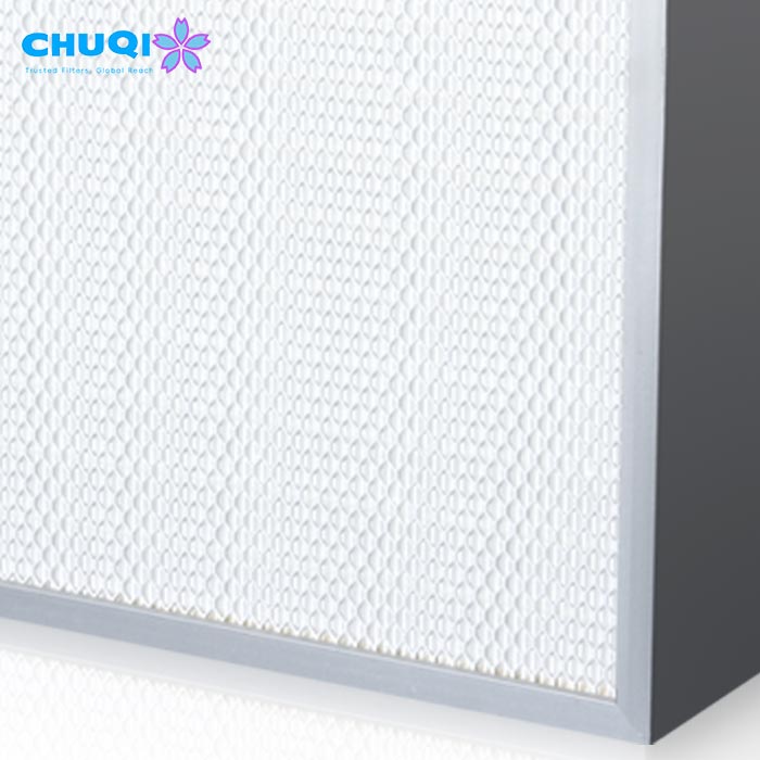
Unfolded media area: The developed area of the filter media inside the assembly.
These values are not interchangeable. The area used in a face-velocity calculation must match the definition used to establish the selected velocity basis.
If the project has not established an appropriate design face velocity, do not choose an arbitrary value merely to complete the calculation. Instead, begin with candidate products and evaluate their documented airflow and pressure-drop performance under the intended conditions.
3. Determine the Number of HEPA Filters in a Parallel Bank
A system’s required airflow may be handled by one larger filter or several smaller filters installed in parallel. The appropriate arrangement depends on product performance, installation space, pressure constraints and maintenance requirements.
The combined face area alone does not establish equivalent performance. Different arrangements can have different flow distributions, internal constructions and supporting structures.
Calculate the Initial Airflow per Filter
For an initial equal-flow assumption across parallel filters:
Q_per filter = Q_total / N
Where:
Q_per filter = initial airflow assigned to each filter in m³/h
Q_total = total airflow through the parallel bank in m³/h
N = number of parallel filters
For a total airflow of 3,600 m³/h and four parallel filters:
Q_per filter = 3,600 / 4
Q_per filter = 900 m³/h
Each filter would carry 900 m³/h under the equal-distribution assumption.
This is a preliminary layout calculation, not proof of actual installed flow distribution. Inlet geometry, branch resistance, filter condition and the supporting structure can affect the airflow through individual elements.
Estimate Filter Quantity from an Acceptable Operating Duty
If a candidate filter has a reviewed acceptable airflow for the required filtration class, resistance and application conditions, an initial quantity can be estimated using:
N = round up (Q_total / Q_acceptable per filter)
The result is rounded up to the next whole number.
The acceptable airflow must correspond to the proposed product configuration and operating conditions. A catalogue value labelled “rated airflow” or “maximum airflow” should not be adopted without checking the associated performance data.
After estimating the quantity, recalculate the per-filter duty and assess the complete installation, including frames, seals, flow distribution and replacement access.
Do Not Confuse Series Stages with Parallel Capacity
In a conventional series flow path without bypass or intermediate branching, the same volumetric flow passes through successive filtration stages under comparable conditions.
A prefilter followed by a HEPA filter does not divide the system airflow between the two stages. Each stage must be evaluated for the flow passing through it.
Adding another filtration stage in series is not equivalent to adding parallel airflow capacity.
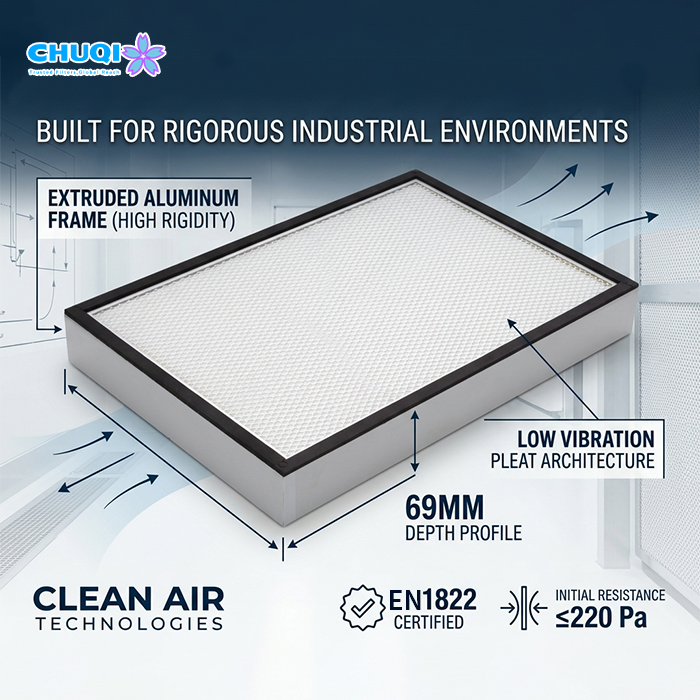
4. Select Filter Depth and Construction Using Performance Data
Filter width and height do not determine the required depth or establish airflow capacity.
The appropriate construction depends on filtration performance, media arrangement, operating airflow, resistance target, available space and environmental conditions.
Why Identical Dimensions Do Not Guarantee Identical Performance
Two HEPA filters with the same external dimensions may differ in media area, internal flow paths and construction. Their airflow and pressure-drop characteristics may therefore differ.
A dimensional match is not a performance match.
Additional depth or media area may create design opportunities, but neither automatically doubles airflow capacity or halves pressure drop. The result depends on the complete filter construction and its performance at the required operating point.
Keep Mandatory Filtration Requirements Fixed
If a project specifies a filtration class, retain that requirement unless a change is formally approved by the responsible party.
A lower-resistance option with a different filtration class is an alternative, not evidence that the original requirement has been met.
Before approving a candidate, verify its applicable filtration performance, airflow and resistance data.
For a broader parameter checklist, see our guide to HEPA filter specifications.
5. Check Pressure Drop at the Required Airflow
A HEPA filter is not suitable merely because its stated airflow matches the system requirement. Its resistance must also be compatible with the pressure available to the filtration stage.
Establish the Pressure Available to the HEPA Filter
The fan serves the complete air path. Prefilters, ductwork, bends, dampers, housings and process components can all contribute to system resistance.
Consequently, the fan’s stated pressure should not automatically be assigned in full to the HEPA filter.
The available pressure must be assessed at the relevant operating point, using a consistent pressure basis. Static-pressure values, total-pressure values and local differential-pressure readings should not be mixed without an appropriate engineering assessment.
Illustrative Pressure-Budget Calculation
Assume an engineering assessment establishes the following values at the required airflow:
Available system pressure: 800 Pa
Other system losses: 450 Pa
The preliminary pressure remaining for the HEPA stage is:
Available pressure for HEPA stage = 800 − 450
Available pressure for HEPA stage = 350 Pa
If a candidate filter has an initial resistance of 240 Pa at the same required airflow and under comparable test conditions, it falls within the preliminary 350 Pa pressure budget.
However, the remaining 110 Pa is not automatically an approved filter-loading allowance. The assessment must also consider resistance changes during service, airflow control, other changing system losses and applicable maintenance criteria.
These figures illustrate the method only. They are not a fan selection, a Chuqi product specification or a performance commitment.
Check More Than the Clean-Filter Condition
A clean HEPA filter may meet the airflow requirement at initial installation, but its resistance can change during service.
The sizing review should establish how the system responds to increasing resistance and which maintenance criterion applies. A maximum allowable differential pressure is not automatically the correct filter replacement setting.
For more detail, see our guide to HEPA filter pressure drop and specification.
6. Verify Housing Compatibility and Maintenance Access
A filter that meets the calculated airflow and resistance requirements may still be unsuitable if it cannot be installed, sealed or replaced correctly.
Confirm Actual Dimensions and Tolerances
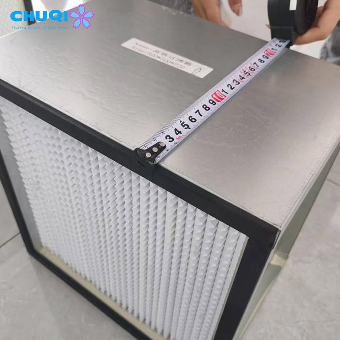
Use the approved drawing or installation specification for final decisions. Confirm width, height and depth, the dimension order, units and relevant tolerances.
Also establish whether the specified dimensions include gaskets, projecting features or other components that affect the installation interface.
Nominal dimensions and labels from an existing filter are useful starting references, but they should not replace an approved interface definition where fit is critical.
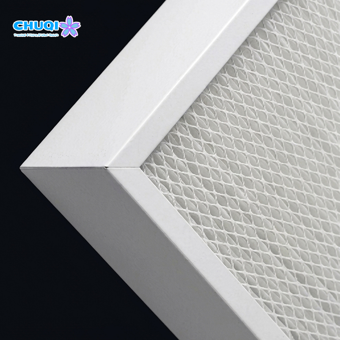
Match the Sealing and Retention Arrangement
Confirm that the proposed filter is compatible with the housing’s sealing and mounting arrangement.
Depending on the design, relevant details may include:
Gasket location and compression requirements
Gel-channel geometry and mating surfaces
Mounting supports and retaining mechanisms
Airflow orientation and installation direction
A filter fitting through the access opening does not establish that it will seat correctly or provide the intended seal.
Check the Filter Removal Path
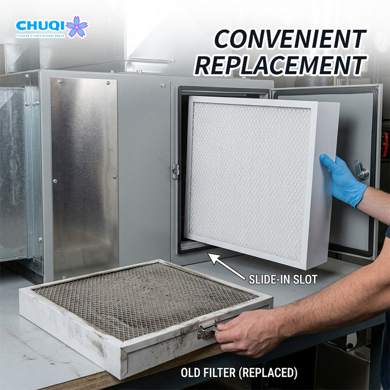
The complete installation must allow the filter to be removed and replaced.
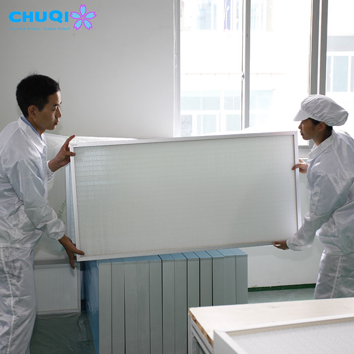
Check the access door, withdrawal path, retaining hardware and nearby components. For larger filters, handling and lifting requirements may also influence the preferred arrangement.
Maintenance access should be considered during sizing, not left until the first replacement.
7. Worked Example: Compare Two Candidate HEPA Layouts
Consider an industrial air system with the following preliminary requirements:
Total airflow through the HEPA stage: 3,600 m³/h
Illustrative face-velocity basis: 1.0 m/s
Calculated total reference face area: 1.0 m²
The next step is to compare candidate configurations, not to order a filter solely from the calculated area.
Option A: One Larger HEPA Filter
Assess whether a candidate filter can handle 3,600 m³/h at an acceptable resistance while meeting the required filtration performance.
Then verify the complete dimensions, housing interface, handling requirements and removal path.
The area calculation alone does not confirm any of these conditions.
Option B: Four Parallel HEPA Filters
Under an equal-flow assumption, each filter would handle:
Q_per filter = 3,600 / 4 = 900 m³/h
Review each candidate filter’s performance at 900 m³/h. Then assess the bank’s overall dimensions, supporting structure, seals, flow distribution and maintenance access.
The number of filters alone does not prove that the bank will satisfy the required duty.
How Should the Two Layouts Be Compared?
| Evaluation Criterion | What to Verify |
|---|---|
| Airflow | Required total and per-filter duty |
| Filtration | Required class and supporting performance data |
| Resistance | Pressure drop at the relevant operating airflow |
| Installation | Complete housing envelope, seals and supports |
| Maintenance | Handling, removal and replacement access |
| Documentation | Approved configuration, drawings and verification scope |
If neither option meets the airflow, resistance and installation requirements together, the preliminary layout needs revision. Possible directions include a different filter construction, greater available depth, a revised parallel arrangement or an equipment-level change.
All numerical values in this example are illustrative. They do not establish a Chuqi product configuration or performance commitment.
Frequently Asked Questions
Q: Can HEPA filter size be determined by airflow alone?
A: No. Airflow helps establish the required duty, but filter selection also depends on filtration performance, pressure drop, housing dimensions, sealing and operating conditions.
Q: Does a larger HEPA filter always have a lower pressure drop?
A: Not necessarily. Pressure drop depends on the complete filter construction and airflow conditions. Compare product-specific performance data at the required operating point.
Q: How do you calculate airflow per HEPA filter in a parallel bank?
A: Divide the total airflow by the number of parallel filters as an initial equal-flow assumption. For example, 3,600 m³/h divided among four filters gives 900 m³/h per filter. Actual distribution must be assessed from the system arrangement.
Q: Can an industrial HEPA filter be replaced with one of the same dimensions?
A: Matching external dimensions does not establish performance equivalence. Confirm the required airflow, filtration class, resistance, installation interface and operating conditions.
Q: What information should I provide when requesting a custom HEPA filter?
A: Start with the required airflow, filtration requirement, available dimensions, existing filter model or equipment drawing. Additional operating and interface details can be confirmed during the technical review.
Need Help Sizing a Custom Industrial HEPA Filter?
If you are developing new equipment, modifying an existing air system or sourcing a replacement filter, Chuqi can discuss your industrial HEPA filter requirements using the information already available.
You can start with an equipment drawing, an existing filter model, required airflow, installation dimensions or housing photographs. You do not need to finalize every parameter before beginning the discussion.
As a source factory offering custom filtration solutions, Chuqi can review the proposed requirements with you and identify which configuration details, performance data and interface specifications need further confirmation.
Explore our industrial HEPA filter product range to review available product options, then contact our team to discuss your application and customization requirements.