
Why Compact Equipment Needs a Different HEPA Filter Design?Compact air filtration equipment often has limited internal space for filter installation. Desktop and wall-mounted air purifiers, laser fume extractors, precision equipment cabinets and compact clean-air units may require HEPA filters with a restricted installation depth.
This creates an engineering challenge: how can a HEPA filter provide sufficient filtration area and maintain acceptable airflow resistance when the available space is limited?
A conventional deep-pleat filter may not fit the equipment housing. Reducing the filter depth, however, can limit pleat height and effective media area. If the required airflow remains unchanged, the resulting increase in media velocity may lead to higher initial pressure drop.
The challenge is not simply making the filter thinner. It is balancing several design factors:
Installation depth: The filter must fit within the available equipment cavity.
Effective media area: The pleated media must provide sufficient filtration surface.
Pleat geometry: Pleat height, pitch and count influence airflow passages and media utilization.
Initial pressure drop: Filter resistance must be compatible with the equipment’s fan performance.
Sealing and structural stability: The filter must maintain its shape and prevent air bypass during operation.
A compact HEPA filter should therefore be designed around the equipment’s airflow and installation requirements, rather than external dimensions alone.
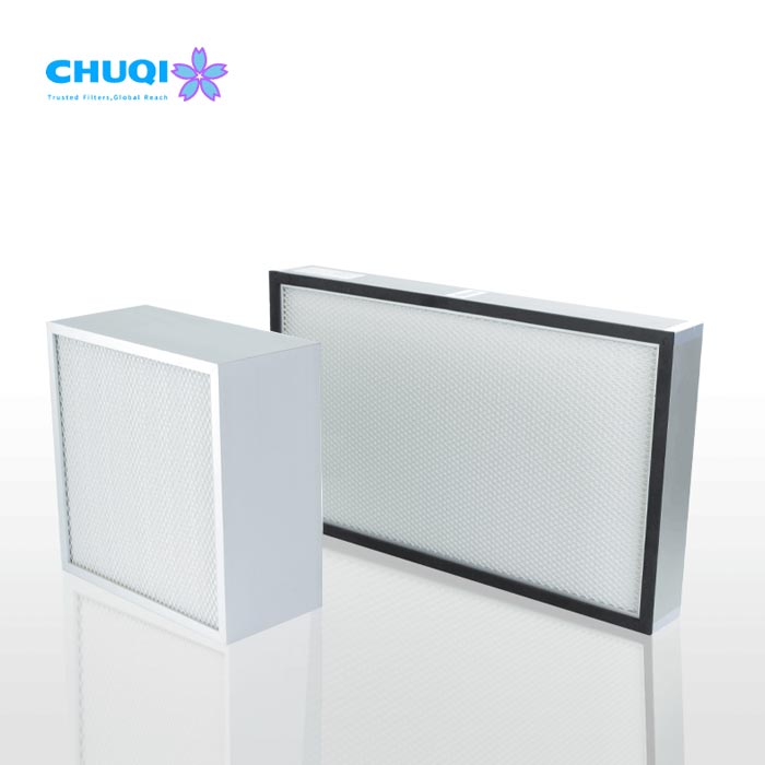
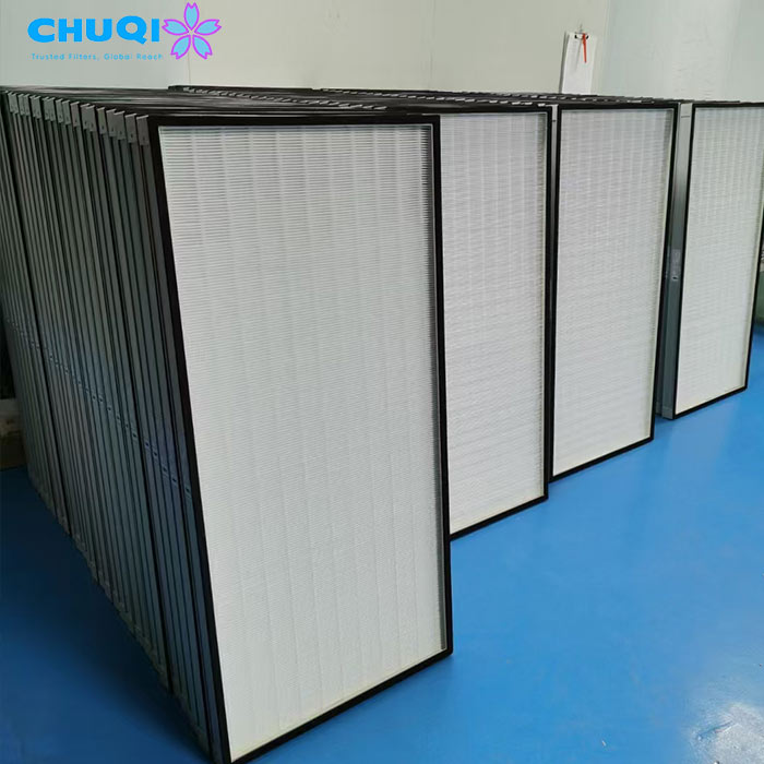

The Engineering Balance Between Filter Depth, Media Area and Pressure Drop
Reducing filter depth affects more than the physical size of a Mini-Pleat HEPA filter. It can change the available media area, airflow distribution and resistance of the completed assembly.
1. Effective Media Area and Face Velocity
The effective filtration area is determined by the amount of media installed in the filter and how effectively that media participates in filtration.
For a given airflow, reducing the effective media area increases the average velocity through the media. Higher media velocity generally leads to greater airflow resistance, although the actual pressure-drop change also depends on media permeability and filter construction.
Several factors influence the available media area:
Pleat height: Shorter pleats provide less unfolded media area when other design variables remain unchanged.
Pleat count: More pleats can increase theoretical media area, but only when sufficient spacing is maintained.
Pleat pitch: The distance between adjacent pleats determines the available airflow passages.
Media permeability: Different media structures produce different pressure-drop characteristics at the same airflow velocity.
This explains why a thin filter cannot be evaluated by overall depth alone. Two filters with similar external dimensions may have different effective media areas and initial resistance because of differences in pleat geometry and media construction.
For applications where installation depth is not severely restricted, a conventional Mini-Pleat HEPA Filter configuration may provide more flexibility in filter geometry and media area.
2. The Pleat Crowding Trap: Why More Pleats Do Not Always Improve Performance
Increasing the pleat count may appear to be a straightforward way to increase media area within a compact filter. However, packing pleats too closely can restrict the airflow passages between adjacent folds.
When pleat spacing becomes insufficient:
Airflow channels may become restricted.
Velocity distribution between pleats may become uneven.
Adjacent media surfaces may not be fully utilized.
Local resistance can increase.
The theoretical media area may exceed the area effectively used during operation.
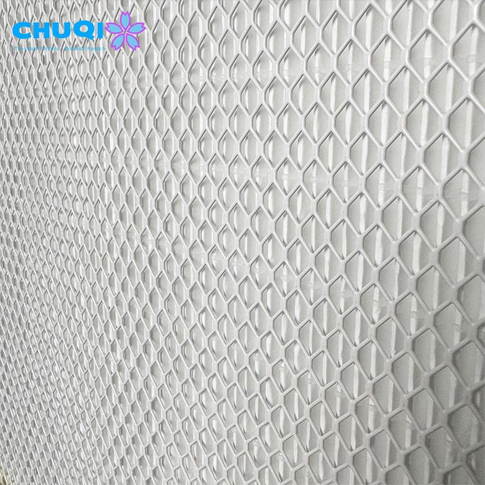
Hot-melt adhesive beads also influence pleat spacing. Their position, width and consistency help maintain the intended pleat geometry and prevent adjacent media surfaces from collapsing or sticking together.
The goal is not to maximize pleat count. It is to create a stable pleat arrangement that provides useful filtration area while allowing air to pass through the media without excessive restriction.
More pleats do not automatically mean lower pressure drop. Effective media utilization and airflow distribution matter just as much as the total unfolded media area.
3. Filter Resistance and Fan Operating Point
A HEPA filter does not operate independently of the equipment fan.
The fan operating point is determined by the intersection of the fan performance curve and the system resistance curve. The filter contributes to total system resistance alongside other components such as ducts, grilles, cooling coils and internal air passages.
A compact filter with excessive initial resistance may reduce the airflow delivered by the equipment, particularly when the fan has limited static-pressure capability.
When evaluating a thin-profile HEPA filter, consider:
Required operating airflow
Filter initial pressure drop at that airflow
Available fan static pressure
Resistance from other system components
Expected pressure-drop increase as the filter collects particles
A suitable design must work within the actual fan and system performance characteristics, rather than relying on filter dimensions alone.
Three Design Variables in Thin-Profile Mini-Pleat HEPA Filters
The performance of a compact Mini-Pleat HEPA filter depends on the interaction between pleat geometry, filter media and frame construction. These elements need to be considered together because a change in one can affect the others.
1. Hot-Melt Bead Geometry and Pleat Pitch Control
Hot-melt adhesive beads help maintain the spacing between adjacent pleats and preserve the intended filter geometry.
In a thin-profile filter, pleat spacing is particularly important because the available internal depth is limited. If the beads are positioned too closely or applied inconsistently, the media channels may become restricted.
Important design considerations include:
Bead spacing: Must maintain adequate separation between adjacent pleats.
Bead consistency: Uneven adhesive application can cause irregular pleat geometry.
Bonding strength: The adhesive must hold the pleats in position under the intended airflow conditions.
Pleat stability: The structure should resist deformation during handling, installation and operation.
The objective is to maintain consistent airflow passages throughout the filter, not simply to fit the maximum possible number of pleats into the available space.
2. Glass Microfiber vs. ePTFE-Based Filter Media
Glass microfiber and ePTFE-based media are two material systems that may be considered for high-efficiency filtration applications. Their suitability for compact HEPA filter designs depends on their specific construction and performance characteristics.
| Design Consideration | Glass Microfiber Media | ePTFE-Based Media |
|---|---|---|
| Filtration structure | Fine-fiber media structure | Membrane-based structure, often combined with support layers |
| Airflow resistance | Depends on fiber structure, thickness and permeability | Depends on membrane characteristics and composite construction |
| Mechanical considerations | Media integrity during pleating and assembly requires attention | Membrane and support-layer integrity must be maintained |
| Design considerations | Media area, pleat stability and handling | Composite structure, bonding and sealing compatibility |
Neither material is automatically better for every compact filter.
The selection should consider the required filtration efficiency, airflow, initial pressure drop, mechanical requirements and operating environment. Actual pressure-drop performance must be evaluated using the specific media grade and completed filter configuration.
3. Frame Wall Thickness and Structural Rigidity
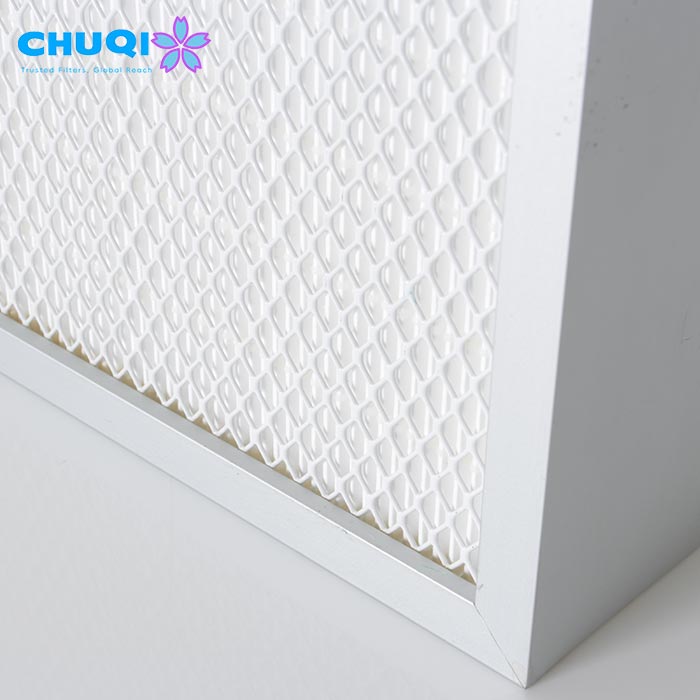
In a compact filter, the frame occupies part of the available installation space. Its design therefore affects both structural stability and the usable filtration area within the equipment housing.
Common frame options include:
Extruded aluminum: Provides a rigid frame structure and can be suitable for applications requiring dimensional stability.
Folded galvanized steel: Offers a metal-frame option with different thickness and structural characteristics depending on its design.
Cardboard frames: May be suitable for selected indoor applications where the operating environment and mechanical requirements permit their use.
Frame selection should consider more than material strength. Wall thickness, connection methods, corner construction and mounting conditions all affect the completed filter’s rigidity.
For compact equipment, an overly thick frame can reduce the available airflow opening. Conversely, a frame with insufficient rigidity may deform during installation or under pressure loading.
Faceguards and protective screens can provide additional mechanical protection for the filter media, particularly where the filter may be handled or replaced frequently. Their design should avoid unnecessarily obstructing the airflow.
The best frame configuration is one that provides sufficient mechanical support without consuming more installation space than necessary.
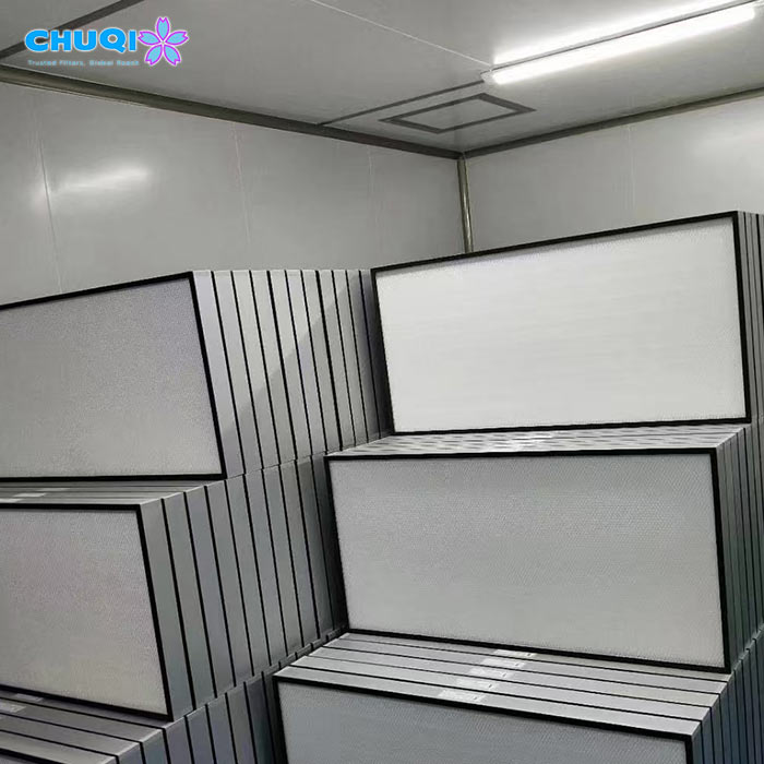
Mini-Pleat HEPA Filter Depth: An Engineering Selection Guide
Different filter depths offer different possibilities for pleat geometry, media area and structural design. The following table provides a preliminary engineering comparison rather than fixed performance specifications.
| Filter Depth | Engineering Trade-Off | Design Focus | Typical Equipment Scenarios |
|---|---|---|---|
| Ultra-Thin (25–35 mm) | Limited pleat height and media area; more sensitive to pleat crowding and sealing problems | Pleat spacing, low-resistance media, frame rigidity and bypass control | Compact medical devices, desktop air cleaners, slim air cabinets |
| Compact (40–55 mm) | More flexibility in pleat configuration and effective media area | Balance media area, pressure drop and structural stability | Laser fume extractors, benchtop enclosures, compact FFUs |
| Slim (69–80 mm) | Greater flexibility in filter geometry and media arrangement | Media area, airflow distribution and dust-loading capacity | Terminal filtration modules and selected air-handling equipment |
How to Interpret the Selection Matrix
25–35 mm: When installation space is extremely limited
Ultra-thin filters are relevant when the equipment housing has very little room for filtration. In these designs, pleat spacing, media permeability and sealing details become especially important because there is less room to compensate for inefficient media utilization.
40–55 mm: When more design flexibility is available
This range may provide additional room for pleat height and media arrangement while retaining a compact overall design. It can be a useful starting point for equipment where both installation depth and airflow performance are important.
69–80 mm: When a deeper compact configuration is possible
A deeper configuration may provide greater flexibility in pleat geometry and effective media area. Whether it improves service life or pressure drop depends on the specific media, airflow and filter design.
Match Filter Resistance to the Fan, Not Just the Filter Depth
Filter depth alone cannot determine the required fan static pressure.
The fan must overcome the combined resistance of the filter and the rest of the air system. A compact filter with low initial resistance may be more suitable for a small fan with limited pressure capability, but the final operating airflow still depends on the complete system.
For this reason, filter depth, media area and initial pressure drop should be considered together with the fan performance curve.
Housing Fitment, Sealing and Installation Challenges
A compact HEPA filter may have suitable filtration performance but still fail to work properly if it does not fit or seal correctly within the equipment housing.
In thin-profile designs, limited frame width and reduced structural depth can make installation and maintenance more demanding.
1. Dimensional Tolerance and Installation Clearance
The filter frame must fit the equipment cavity without excessive force or unnecessary clearance.
Insufficient clearance can make installation and replacement difficult. Excessive clearance, on the other hand, can create gaps around the filter and increase the risk of bypass leakage.
Dimensional tolerance should be designed around:
Internal housing dimensions
Filter frame dimensions
Mounting and retention method
Gasket thickness and compression requirements
Installation and replacement access
A universal negative tolerance should not be applied to every compact filter. The appropriate clearance depends on the equipment structure and sealing arrangement.
2. Gasket Compression and Bypass Leakage
The gasket creates a sealing interface between the filter frame and equipment housing.
Common gasket materials include EPDM foam, silicone and polyurethane-based sealing systems. Their suitability depends on the operating temperature, compression characteristics, chemical exposure and expected service conditions.
Important considerations include:
Compression behavior: The gasket must compress sufficiently to create a seal without placing excessive force on the frame.
Recovery characteristics: The material should retain suitable sealing behavior after compression.
Temperature compatibility: The gasket must remain suitable for the equipment’s operating environment.
Sealing continuity: Gaps at corners or joints can create bypass paths even when the filter media itself is intact.
For thin-profile filters with narrow frames, the available sealing surface may be limited. The gasket arrangement and frame design should therefore be considered together.
3. Frame Rigidity and Filter Handling
Thin-profile filters can be more sensitive to handling forces, particularly when the frame has limited depth or narrow support surfaces.
During installation and maintenance, pressure applied to the frame or exposed media can cause deformation or damage.
Depending on the filter construction, useful design features may include:
Reinforced frame corners
Suitable faceguards or protective screens
Pull tabs or accessible handling points
A mounting arrangement that supports the frame evenly
These features can help reduce handling damage and make filter replacement easier in compact equipment.
4. Checking for Bypass Leakage
If downstream particle readings are higher than expected, the problem may not originate from the filter media.
Potential leakage paths include:
Gaps between the filter frame and housing
Damaged or uneven gaskets
Distorted mounting surfaces
Incomplete sealing at frame corners
Damage to the media-to-frame bonding interface
Inspection should distinguish between leakage through the filter assembly and air bypassing around its perimeter. This distinction helps identify whether the problem lies in the filter itself, the gasket or the equipment housing.
Engineering Collaboration for Custom Thin-Profile HEPA Filters
Limited installation space doesn’t have to mean compromising filtration performance. Chuqi manufactures its own air filter media and finished filters, helping adapt filter dimensions, pleat configurations and frame structures to different equipment requirements.
Developing a compact HEPA filter for your equipment? Contact our team to discuss your application and customization needs.
Looking for standard configurations? Explore our Mini-Pleat HEPA Filters product page.
Frequently Asked Questions About Compact Mini-Pleat HEPA Filters
1. What is a thin-profile Mini-Pleat HEPA filter?
A thin-profile Mini-Pleat HEPA filter is a compact high-efficiency air filter designed for equipment with limited installation depth. Its pleated media provides an expanded filtration surface within a relatively shallow housing, making it suitable for compact air purification equipment and specialized industrial systems.
2. Does a thinner HEPA filter always have a higher pressure drop?
Not necessarily, but reducing filter depth can limit pleat height and available media area. If the required airflow remains unchanged, the resulting increase in media velocity may increase pressure drop. Actual performance also depends on media permeability, pleat geometry, effective filtration area and airflow distribution.
3. Can increasing the pleat count reduce the pressure drop of a compact HEPA filter?
Increasing pleat count can increase the theoretical media area, but it does not automatically reduce pressure drop. If pleats are packed too closely, airflow passages may become restricted and air distribution may become uneven. Pleat spacing and geometry must allow the available media area to be used effectively.
4. What is the recommended depth for a compact Mini-Pleat HEPA filter?
There is no single recommended depth for every compact filtration application. The suitable depth depends on the available housing space, target airflow, filtration requirements, media characteristics and fan performance. Shallow configurations may suit highly restricted equipment cavities, while deeper designs can provide more flexibility in pleat geometry and media area.
5. How do I select the right filter media for a thin-profile HEPA filter?
The selection should consider filtration efficiency, air permeability, mechanical properties, pleating suitability and the required operating environment. Glass microfiber and ePTFE-based media have different material structures, and their actual pressure-drop performance depends on the specific media construction and completed filter design.
6. Why is pleat spacing important in a compact HEPA filter?
Pleat spacing determines how much room is available for air to pass between adjacent pleats. Insufficient spacing can restrict airflow, create uneven velocity distribution and reduce the effective use of the filter media. A well-designed pleat arrangement balances media area with adequate airflow passages.
7. What causes bypass leakage in thin-profile HEPA filters?
Bypass leakage can occur when the filter does not seal properly against the equipment housing. Common causes include dimensional mismatch, unsuitable gasket compression, uneven mounting pressure and distorted installation surfaces. Thin-profile designs require particular attention to frame rigidity and sealing-interface design.
8. Can a Mini-Pleat HEPA filter be customized to fit a compact equipment housing?
Yes. Filter dimensions, overall depth, frame construction, pleat arrangement and sealing details may be adapted to suit a specific equipment design, subject to manufacturing feasibility and performance requirements. Equipment drawings and housing dimensions are useful starting points for evaluating a custom configuration.
9. What information is needed to develop a custom thin-profile HEPA filter?
The most useful starting information includes the available housing dimensions, maximum filter depth, target airflow, available fan static pressure and required filtration efficiency. Operating temperature, humidity, gasket preference and installation details also help determine a suitable filter construction.
10. How can I determine whether a compact HEPA filter will meet my equipment’s airflow requirements?
The filter’s initial pressure drop should be evaluated at the required airflow and considered alongside the resistance of the complete air system. The fan performance curve and system resistance curve determine the operating point. Testing the filter at relevant airflow conditions, followed by equipment-level evaluation, helps assess whether the design meets the intended airflow target.